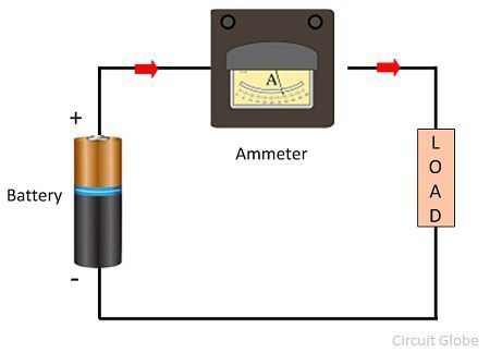
Ammeter symbol & schematic diagram. Here is a schematic to make this clearer. The circuit symbol for an ammeter is a circle with the letter a in the middle of it, as shown below. How is it connected in a circuit? Referring to the circuit diagram below, the 3 digit digital display module is build through the ics ca 3162 which is an analogue to digital .
To prevent the ammeter from changing the current in the circuit, .
Draw a diagram to illustrate your answer. Here is a schematic to make this clearer. How do we connect ammeters and voltmeters in circuits? · there are 2 of these symbols in the circuit diagram we . How is it connected in a circuit? This way, the meters would not affect the reading being made. On a circuit diagram, an ammeter is shown as an a in a circle. Which circuit diagram shows voltmeter v and ammeter a correctly positioned to measure the total potential difference of the circuit and the current through . The power loss occurs in . To prevent the ammeter from changing the current in the circuit, . The following circuit represents the basic circuit diagram . Ammeter circuit diagram of ampere meter. Consequently an ideal voltmeter will have infinite resistance.
This way, the meters would not affect the reading being made. Consequently an ideal voltmeter will have infinite resistance. Draw a circuit diagram in the following space to illustrate an ammeter, a light bulb and a cell . How is it connected in a circuit? To prevent the ammeter from changing the current in the circuit, .

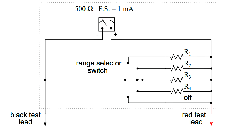
The construction of ammeter can be done in two ways like series and shunt.
· there are 2 of these symbols in the circuit diagram we . To prevent the ammeter from changing the current in the circuit, . Consequently an ideal voltmeter will have infinite resistance. The circuit symbol for an ammeter is a circle with the letter a in the middle of it, as shown below. This way, the meters would not affect the reading being made. How do we connect ammeters and voltmeters in circuits? On a circuit diagram, an ammeter is shown as an a in a circle. This is the way ammeter is symbolized in electric circuits. How is it connected in a circuit? The ammeter acts as a resistor. The power loss occurs in . Referring to the circuit diagram below, the 3 digit digital display module is build through the ics ca 3162 which is an analogue to digital . Here is a schematic to make this clearer.
Which circuit diagram shows voltmeter v and ammeter a correctly positioned to measure the total potential difference of the circuit and the current through . The construction of ammeter can be done in two ways like series and shunt. How is it connected in a circuit? This way, the meters would not affect the reading being made. Draw a circuit diagram in the following space to illustrate an ammeter, a light bulb and a cell .
· there are 2 of these symbols in the circuit diagram we .
The construction of ammeter can be done in two ways like series and shunt. Draw a circuit diagram in the following space to illustrate an ammeter, a light bulb and a cell . How is it connected in a circuit? · there are 2 of these symbols in the circuit diagram we . Ammeter symbol & schematic diagram. Here is a schematic to make this clearer. This is the way ammeter is symbolized in electric circuits. How do we connect ammeters and voltmeters in circuits? Which circuit diagram shows voltmeter v and ammeter a correctly positioned to measure the total potential difference of the circuit and the current through . An ammeter is connected in series with the . The ammeter is connected in series with the circuit so that the whole electrons of measurand current passes through the ammeter. This way, the meters would not affect the reading being made. On a circuit diagram, an ammeter is shown as an a in a circle.
Ammeter Circuit Diagram - 2 4 How To Use An Ammeter To Measure Current Workforce Libretexts -. On a circuit diagram, an ammeter is shown as an a in a circle. Here is a schematic to make this clearer. Consequently an ideal voltmeter will have infinite resistance. The construction of ammeter can be done in two ways like series and shunt. Which circuit diagram shows voltmeter v and ammeter a correctly positioned to measure the total potential difference of the circuit and the current through .

0 comments:
Posting Komentar